|
A polar histogram is used for the detection of triangles: it is obtained scanning the difference image with respect to a focus, considering every straight line originating from the focus itself and counting the number of overthreshold pixels lying on that line (figure 4.f). The values of the polar histogram are then normalized and a low-pass filter is applied in order to decrease the influence of noise (figure 4.g). The polar histogram presents an appreciable peak corresponding to each triangle. Peaks may have different characteristics such as amplitude, sharpness, or width, depending on the obstacle distance, the angle of view, and the difference in brightness and texture between the background and the obstacle itself. The position of a peak within the histogram determines the angle of view under which the obstacle edge is seen. Peaks generated by same obstacle, for example by its left and right edges, must be joined in order to consider the whole area in between as occluded.
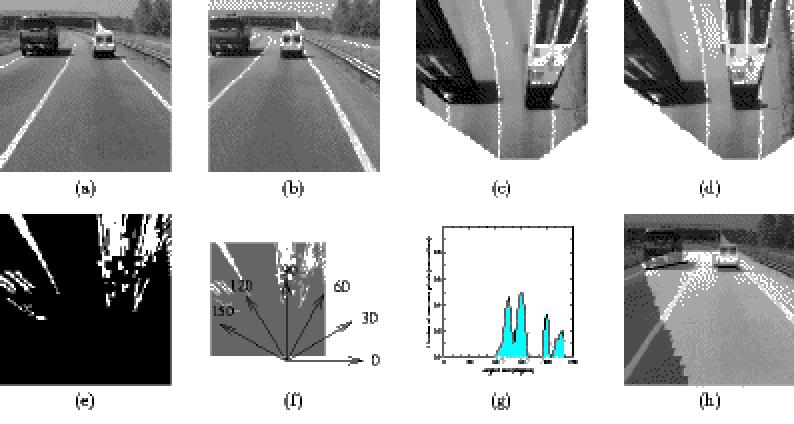
Figure 4: Obstacle detection: (a) left and (b) right stereo images, (c) and (d) the remapped images, (e) the difference image, (f) the angles of view overlapped with the difference image, (g) the polar histogram, and (h) the result of obstacle detection using a black marker superimposed on a brighter version of the acquired left image; the light gray area represents the road region visible from both cameras Starting from the analysis of a large number of different situations a criterion has been found, aimed to the grouping of peaks, that takes into account several characteristics such as the peaks amplitude and width, the area they subtend, as well as the interval between them. After the peaks joining phase, the angle of view under which the whole obstacle is seen is computed considering the peaks position, amplitude, and width. In addition, the obstacle distance can be estimated by a further analysis of the difference image along the directions pointed out by the maxima of the polar histogram, in order to detect the triangles corners. In fact they represent the contact points between obstacles and the road plane and thus hold the information about the obstacle distance. For each peak of the polar histogram a radial histogram is computed scanning a specific sector of the difference image whose width is determined as a function of the peak width[1]. The number of overthreshold pixels lying in the sector is computed for every distance from the focus and the result is normalized. A simple threshold applied to the radial histogram allows to detect the triangles corners position and thus the obstacle distance. The result is displayed with black markers superimposed on a brighter version of the left image; the markers position and size encode both the distance and width of obstacles (see figure 4.h). |